|
During the years I have the WD16H, and while making this website and
answering people on various items, I found that a number of parts are not
given in the spare parts lists or described in the Maintenance &
Instruction Manuals that I have. The consistency with which they are not given is puzzling. Nobody
bothered to mention it, or Norton was not interested in correcting it.
Other parts are prone to failure but their failure is not
always obvious. Additionally it is helpful to have some dimensions of
parts not so readily available anymore like friction discs for front
fork and steering damper.
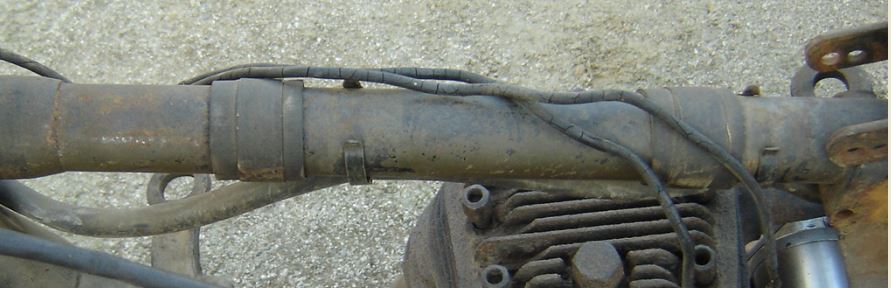
The engineering of the bike is lovely crude. Any superfluous oil is
just discarded on the road through multiple copper pipes. Length and
routing of those pipes hardly ever are original nowadays. They tend to
break off or have been cut short after kinking. If you have to make new
ones, some guidance is given on how to get the original look again. When
building up a bike from parts, some of them are difficult to find as
they are not clearly visible in the illustrated parts list.
Also some special tool are given which can be made to ease
tinkering on the bike.
I hope my experiences can be of help. I expect this to become a small list in the end.
It is not always to be taken as advice. It is always your own decision and
responsibility if you follow what I did/do.
MYSTERIOUS PARTS
Crankcase breather valve.
To alleviate the pressure differences which develop in the crankcase when
the piston is going up and down, a pressure relieve system is usually
utilized. On the 16H and Big 4 engine, this consists of two supplementary
systems, one timed version breathing through the driving side flywheel
into a cavity in the crankcase blowing out of a hole underneath the
driving shaft behind the primary chain case and one ball valve type
breather on the left hand side of the crankcase onto which a copper pipe
is mounted spitting excess oil onto the rear chain and relieving
pressure at the same time. The ball assures that the oily mist is
going one way only.
This copper breather tube, steel ball
valve and the brass nipples are not very obvious in the spare parts list.
It is listed under Transmission as "Crankcase breather, complete with
Pipe" part no. 9531. It would be more appropriate in the Engine
section!
The Maintenance and Instruction manuals do refer to a valve,
without any further description of the configuration and working.
Over time when engines wear and more pressure develops due to gasses
bypassing the piston this breathing system becomes more important (also
less adequate).
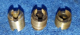
At the same time wear occurs on the screw in the valve reducing the
available aperture for the air to blow through. The steel ball hammers
into the brass and deforms the screw end, which will therefore reduce
the possibility for breathing while you actually would need more. This
will likely result in a leaking engine at all kinds of places.
Pictures below show the valve construction and the wear on the central
screw.
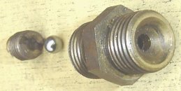
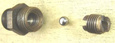
Bottom view crankcase breather
valve
Top view crankcase breather valve
wear on breather bolt, new, medium, severe
Strangely enough, Norton never described this wear nor an
inspection of the valve and similarly no information on the play the
ball should have in the valve.
I assume the ball should lift just enough to have the same aperture surface as the
the hole surface in the screw which is obtained around at 1-1,5 turn from
fully seating.
Overall, the efficiency of this system is to be regarded as theoretical
and unlikely to be working at all rpm's as intended as at higher speeds
the steel ball is supposed to be vibrating at the engine rpm frequency
but its mass may not be willing to comply.
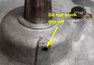
One note of caution, some people block-off the timed breathing aperture
in the crankcase behind the primary case because there will be some oil
dripping from it, especially when the engine is prone to wet-sumping due
to worn oil pump gears and/or prolonged storage.
This is not correct and may lead to more oil consumption/leakage as it
halves the breather capacity.
Rubber, felt and leather washers/distance pieces.
Many bikes have lost their rubber, felt or leather washers over the years.
Many people don't even know there should be any at all. The M&I manual
does sometimes mention them, but although mentioned in the spares lists, they are relatively mysterious.
Between the primary chaincase and the engine crankcase a
rubber washer was used initially but changed to leather from 1942
onwards. Between the primary chaincase and the gearbox a
felt washers was applied.
Felt washers were further used for: clutch nut, gear
change pawl carrier, wheel hub bearings (both sides), inside primary chaincase
between footrest tube and outer casing. Between the top frame tube and
the petrol tank 2 sheet rubber patches were applied, on "later"
bikes (post 1942) these rubber patches were replaced by pieces of felt.
I also added a non standard felt washer between the magneto and the timing chain
case.
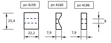
A special hard rubber washer "system" was used on the bolt holding the
Rear Mudguard to the Rear Mudguard Chain Stay Bridge (frame cross brace). The bolt is simultaneously
fixing the Oil Tank Top Attachment Clip (pn 3590). This system consisted
of multiple thick "washers" with 3 different part numbers, 4159,
4160 and 4196, below drawing gives the dimensions as found.
The exact application is difficult to state as even the most original
MC's found had different solutions. One logical sequence found was
short length on mudguard side, channelled version for ribbed mudguard,
other for plain mudguard, followed by long version, a metal washer,
cross tube, oil tank attachment clip, washer and bolt.
Gearbox main axle dished spring washer
The exploded view drawings of the gearbox in the M&I manual as well as various books, show a dished steel spring
washer at the end of the main axle. I personally have never found such a
washer in a gearbox, and wonder if they were actually used on all boxes,
or only the later ones. Its not given in the spare parts list of either
old or newer contracts or postwar civilian lists. The dimensions are I.D.
5/8", O.D. 1 7/16", steel thickness 1/64" and dished height 1/16" as
measured on an original sample.
Clutch Roller Cage with Rollers
The number and dimension of the rollers is not given in either spares
list or maintenance manual. From the M&I manual it can almost be deduced
how many with a small margin of error. In actual fact, 20 rollers are
used 1/4" x 1/4". Post war AMC clutches used 15 rollers of the
same dimension. Not quite sure why the more powerful postwar
machines had less rollers. Only thing I can assume it was an overkill to
use 20 or the material properties had been improved.
Clutch Back Plate
The original military WD16H and Big 4 backplate was a sheetmetal stamping
with a thickness of approx 3 mm. Post war, the early AMC backplates were machined
and have a greater thickness. Later AMC backplates (post 1957?) with incorporated
friction parts may work as well but with the correctly associated plain Clutch
Sprocket. Drawback of using AMC backplate is that the clutch becomes
wider and will interfere with the inner chaincase more easily. A lot of tweeking
may be required to get the parts into such position that they do not rub against each
other.
Kickstarter Axle cork oil retainer washer (3810)
To prevent the oil leaving the gearbox along the kickstarter axle there
is a cork washer fitting in a recess in the gearbox cover.
The washer p/n 3810 is not shown on the M&I manual exploded views.
People have replaced the cork with a proper size O ring.
If you do, make sure it is chemical resistant to the oil. NBR or Viton will
do the job.
Driving Side Main Bearing Distance Piece (4155)
In early 16H and Big4 spare parts lists (upto to 1942), this metal ring is not
mentioned despite the fact that they are mounted in all engines after
1935.
 Main
bearing distance piece as shown in original blueprint of 1935/6, valid
for 16H, Big4, M18, M19, M20 and ES2 Main
bearing distance piece as shown in original blueprint of 1935/6, valid
for 16H, Big4, M18, M19, M20 and ES2
It is placed between the two main bearings at the drive side of
the engine. It is a flat ring with an oil channel at the outer
circumference and 6 holes in the middle (up to 1940 roughly) or 4 recesses on one side
(later version). These recesses are shown in the exploded view of the
Big 4 M&I manual to face towards the inside of the engine. The
written text of "Fitting bearings to crankcase" however
gives no guidelines to the position of these recesses so it is possibly
not important. The exploded view of the engine in the 16H M&I manual
does not show this part at all. Although the
engine will run without it, it seems unwise not to add it. Theoretically
one or either main bearing could slide sideways, more likely in
well-used engines. Missing of this piece in many engines may be
caused by the inconsistent descriptions in both spare parts lists and
maintenance manuals.
See also
Parts drawings for DIY manufacture or reference.htm
Carburetter needle jet
The Needle jet in the 276 carburetter has been described in the
original AMAL specification sheets for WD16H and B4 as "standard". The Spare
parts lists and the VAOS lists describe it just as Needle Jet with part
number AM/4/061.
The Burlen Ltd company, (present official AMAL manufacturer, see links
page) stated that the "standard" part was actually the 1065. These were
not marked. For reason of optimisation, there are alternative needle
jets available
numbered, 105, 106, 107, 108 and 109. The number signifies the internal
diameter in 1/1000th of an inch.
Carburetter needle clip position
Something that crops up all the time is whether you count the needle
clip slot from the top down or bottom up. With all Amal carburettors the
clip position is top down. (ref The Burlen Ltd website).
Fork Spindle Knurled Adjusting Washers (3184)
The drawing of the front fork as given in the Maintenance &
Instruction manual is not completely correct. The drawing only shows 4
knurled washers (10) but it have to be 6 as stated by the spare parts
lists and logic. I adapted the drawing to show the two additional
washers (10) on the bottom rear spindle.
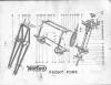 Click picture to enlarge
UNEXPECTED DIFFERENCES
Magdyno platform variations
When restoring a military 16 H or Big 4 from scratch, one
unfortunate finding could be that the timing chain as dictated by
the Magdyno sprocket does not run in line with the driving timing
sprocket.
When using the wrong platform, there is no gap between the rear of
the timing chain cover and the Magdyno. When using the correct
platform there should be a clear gap between those parts. I cannot
give an exact measurement for the gap as there are many variations
but some measured results are around 3/16" (4,7) mm. To prevent
muck to enter the timing chest through this gap I have made a
fitting felt washer mount between the Magdyno and the timing chain
with such dimension that it does not interfere with the rotating
Magdyno shaft and is not to obtrusive when looking at it from the
outside.
The in-line deviation will not happen (on military bikes) when
using the cast iron version as made during the war (casting number
12311), but it can happen when applying the aluminium version as
used before and after the war. The correct aluminium version has a
casting number 11699 on it. One incorrect aluminium version has a casting
number 13814 on it, there may be more aluminium casting numbers.
The civilian Norton part number changed from 3711 (pre war military
and civilian prior to 1938) to 3711A for the cast iron version to
A2/117 in 1946 and 1947.
The 1938/39 civilian Norton part number was 8918, but its not clear
yet if they deviated in dimensions or casting number and whether
they are identical to the pre war 1938/1938 civilian version.
There has also been a part number C2/117 but its not known (at this
moment of writing) in what sense it differs from A2/117 or 3711(A).
The number 13814 was found on a platform labelled C2/117.
NOT SO VISIBLE FAILURES (AND SPARES)
Main Gear Wheel Sleeve Bearing Roller Retainer Washer.
Pictures of the "exploded view" gearbox show that the rollers in
the main gear wheel are neatly housed. What it does not show is that the
rollers are closed into the main gear wheel by a steel washer, against
which the bronze clutch thrust washer rotates when activating the clutch.
Look at the picture given in the
gearbox and transmission
page where I added the washer for clarity.
This hardened steel washer has the tendency to fracture. Two of the 3
gearboxes I have showed this to be the case. The washer is given in the
spare parts lists (all) under no 3598 (Main Gear Wheel Sleeve Bearing
Roller Retainer Washer). I have however not been able to find
original replacements for them, and had them made from a cold work tool
steel (AISI D2 or UNS T30402) and hardened to 59 Rc. Remains of the
original were measured to be 60 Rc so I think I am close enough. See
Parts sketches for manufacture or reference page for dimensions.
Loosening clutch nuts
On some bikes, you see an additional disc in the large depression
produced in the primary chain case to house the clutch. This is usually
the result of adjustment of the clutch disengagement while actually the
clutch nut has come loose.
So if you ever have the urge to adjust the clutch disengagement stroke, first check the central
nut on the clutch. Despite the spring washer behind it, it loosens on
occasion.
OIL AND GREASE STUFF (See alo the
running a 16H or Big 4 page)
Oil non-return valves.
Anybody not having used his bike for some time will have experienced the
blubbering noises and heavy kick starter actuation when trying to start his
machine. I know, everybody has a perfect oil pump, but me?
The oil tank has drained itself into the engine
crankcase after finding its way past the gears of the oil pump.
A safe solution is to add a non-return valve into the oil line. Although
I made one myself, you can also buy them on the market.
An oil tap works but with rising age is not the best solution,
unfortunate experience!
Valve grease nipples.
One of the most amazing features on the 16H engine are its valves. There
are grease nipples on the valve guides as a token addition to subdue valve
stem wear. Initially I used to give them a squirt of high temp molybdenum
based grease. This usually resulted in a fairly sizable smoke curtain at
the beginning of a trip.
I stopped greasing them as I don't think it has any use. I am now about
25.000 miles further since I stopped greasing and it still works. I know
I don't have the maximum compression, and I don't go faster than 50 MPH
anyhow because that is a very uncomfortable speed on a dinosaur
suspension.
Oil regulating grub screw on top of timing cover
An often asked question reaching me is about the setting of the grub
screw valve on top of the timing cover.
The setting of this grub screw regulates the amount of oil being fed to
the rear of the piston/cylinder.
It is not properly described in the military Maintenance and Instruction
manuals people usually use as guide.
The setting of this was done at the factory and should normally not need
to be touched. After 60 odd years however some cleaning of the insides
may be required or the workmanship of previous owners needs to be
checked.
The standard setting of this screw is one turn from the fully closed
position. (According to WC Haycraft in 1936 and EM Franks in 1952, page
11 to 15).
Its difficult to say if this is still correct for all engines, but
depending on the state of the engine it may need some adjustment.
It should be adjusted such that there is a minimal amount of smoke
coming from the exhaust. As the smoke from the exhaust does not only
come from this setting, its a setting with lots of possible positions.
The standard setting is therefore the most likely correct one.
| 