|
Gearbox and gear change mechanism evolution
The gearbox as used by Norton was actually a design from Sturmey
Archer which was bought by Norton but the boxes themselves were
built by Burman. Modification of the SA design possibly done by
Burman but the gear change mechanism was a Norton patent of 1935.
(424,154. Controlling variable speed gearing. NORTON MOTORS, Ltd.,
and CARROLL, A.)
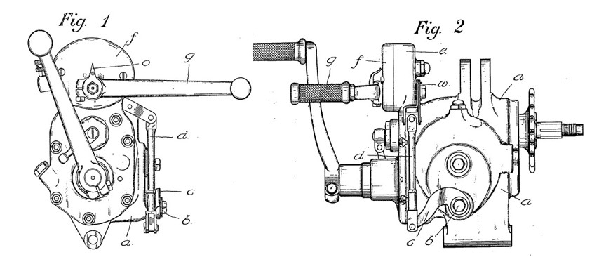
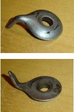
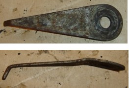
Drawings from the patent show the initial
configuration of the ratchet lever with the swivel at the end for
fixing the gearbox control rod. This version was replaced in 1937 by
a straight ratchet lever without a swivel. From 1938 onwards, 2
additonal nuts were applied at the rear of the head to improve the
fixing of the Stop Studs for Pawl Carrier to the dolls head housing.
These additional nuts required a new ratchet lever to remain clear
of the nuts.
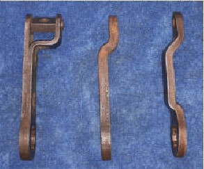
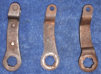
evolution of ratchet levers, from left to right, pre 1937, 1937 and post
1937 version.
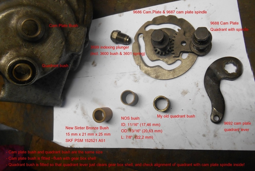
Further changes over time was the introduction of
bushes on the return spring cover plate and the cam plate, an
obvious attempt to improve the wear resistance of the support of the gear
change lever. This was retrospectively applied on earlier machines,
based on DME B.304 dated 7-9-1942. Not absolutely certain which
solution in the picture of the camplate (steel bush or bronze bush)
was the Norton applied change or the workshop version based on the
DME.
The application of the bushes required a bigger hole in the gear
change mechanism cover. Up to late 1939 there was no brass gear
position indication plate on the dolls head. This was likelt
introduced due to the influx of large numbers of non-experienced
motorcyclists in the military. The cover of the earlier change
mechanism showed a small vertical stripe in the bottom of the first
"o" of the Norton name to indicate neutral only. The brass plate
showed all 4 gears and neutral.
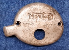 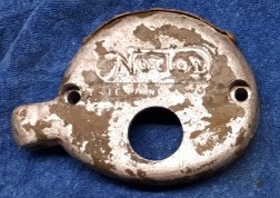
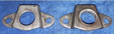
Gear change mechanism covers at left early without brass
indication plate and small hole, at right later with brass plate
riveted to the top of the cover and larger hole to accommodate the
bush in the return spring cover.
Gear change indicator at left used up to 1939
in combination with early cover, at right 1939 and up in
combination with later cover.
no exact change date known. As covers were made before changes were
introduced, early covers can be found having been modified with the
brass plate.
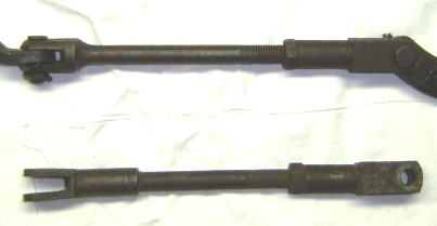
Upper one is early production gear control rod, lower one a later production,
unknown when latter was introduced as part number never changed. |
|
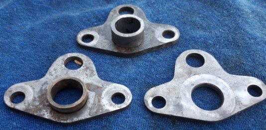
Gearbox castings, identification and ratio's
The gear ratio's given in the Norton Maintenance
and Instruction Manuals and as often found in various contemporary
books are slightly confusing when looking for a proper
gearbox for your bike. The ratio's given are basically the ratio's
of the entire transmission system from engine sprocket to rear
wheel drum mounted sprocket, and not of the gearbox itself. Civilian
16H and Big4, and WD16H gearbox shells were all identical. Most
common casting
numbers were N8001 and N8001-3, some deviations are observed which
may have been production errors as internals were correct. Very
early (1936) gearboxes did not have a drain plug at the bottom rear
of the casting but it was standard from 1937 onwards.
Several serial number prefixes are observed, following explanation
is conjecture but with logic. As Burman made gearboxes for other
motorcycle manufacturers as well it is believed that the "N" in the
serial number generically stands for Norton, the other letters for
the specific application.
|
Serial prefix |
GEARBOX RATIO'S |
Application |
|
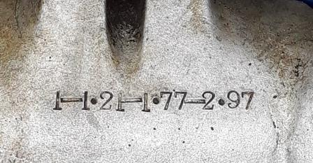
SN |
1
-
1.21 -
1.77 -
2.97 |
Standard for WD16H and civil road going models |
|
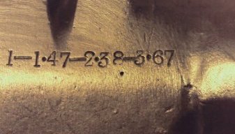
TNS |
1 -
1.47 -
2.38 -
3.67 |
Military Big 4 |
|
IN |
1 - 1.1
- 1.33 - 2.33 |
International (all racing models) |
|
TN |
1 -
1.33 - 2.16 - 3.2 |
Trials models |
Especially for the Big4 restorers its
difficult to find a correct bearbox because there are still loads of
WD16H gearboxes around, but
not many WDBig4 gearboxes.
It has to be kept in mind however that if you are restoring a prewar
civilian Big4, the civil/military 16H gearbox is correct.
The military Big4 received a trials gearbox with a different, lower,
gearing to haul the heavy sidecar through
mud.
Unfortunately ratio's were not always applied making it difficult to
ascertain if they were specific for military application, below some
examples for WD16H en WDBig4.
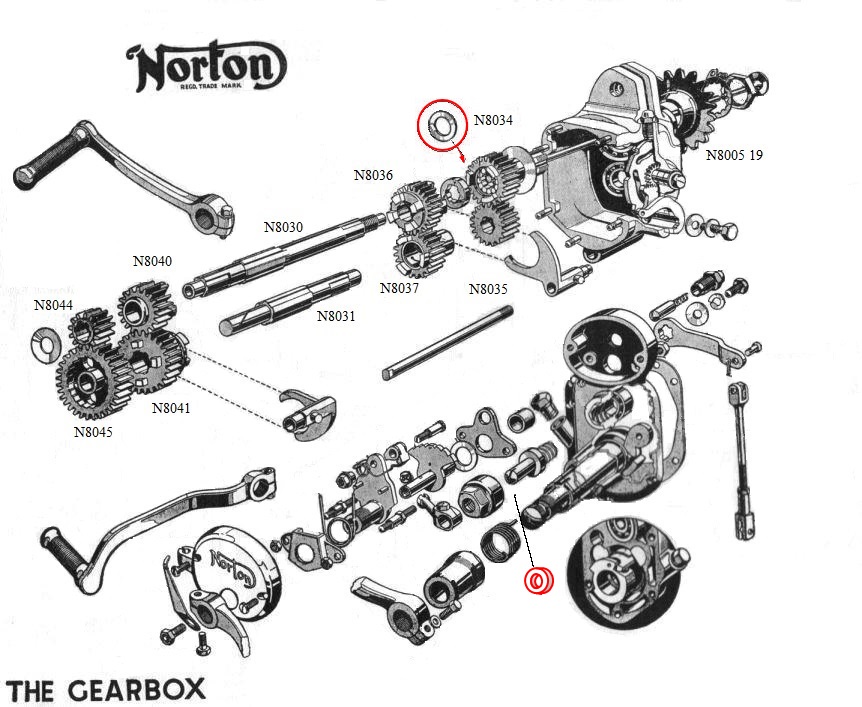
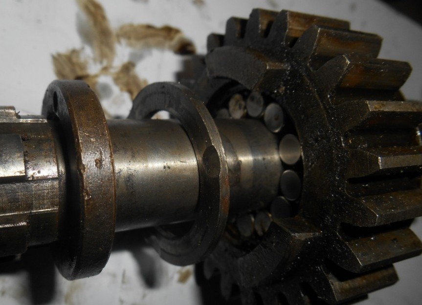
Survey of gearbox internals
showing
identification numbers as given on the individual gear wheels,
number of teeths and Norton spare part
number, usually engraved into the gear wheel by the N80xx number.
(See also exploded view below)
Survey of gears for military and civilian
16H and Big4 MC's
|
Model
|
WD16H
and civil 16H and Big4 |
WDBig 4 |
|
|
Civ 16H and Big4 |
WD16H |
|
AXLES |
NUMBER |
PART # |
PART # |
NUMBER |
-- |
PART # |
|
Main Axle |
N3030 |
3318 |
3319 |
-- |
-- |
3319 |
|
Layshaft |
N3031 |
9672 |
3320 |
-- |
-- |
3320 |
|
GEARS |
NUMBER |
TEETH # |
|
NUMBER |
TEETH # |
PART # |
|
Main Gear wheel |
N8034 |
24 |
9673 |
N8047 |
25 |
2266 |
|
Layshaft Pinion |
N8035 |
18 |
9678 |
N8046 |
17 |
2268 |
|
Main Axle Sliding Pinion |
N8036 |
22 |
3322 |
N8162 |
21 |
2031 |
|
Layshaft Free Pinion |
N8037 |
20 |
9679 |
N8163 |
21 |
2034 |
|
Main Axle Free Pinion |
N8040 |
18 |
9676 |
N8160 |
16 |
2032 |
|
Layshaft Sliding Pinion |
N8041 |
24 |
9680 |
N8161 |
26 |
2035 |
|
Main Axle Pinion |
N8044 |
13 |
9677 |
N8048 |
12 |
2267 |
|
Low Gear and Kickstarter Wheel |
N8045 |
29 |
9681 |
N8049 |
30 |
2669 |
Survey of
Sprocket teeths on the various positions
|
Model |
WD16H
|
WDB4
|
Civil 16H and
B4 (solo) |
Civil 16H and
B4
(sidecar) |
|
PART |
|
Engine Sprocket |
18 |
18 |
19 |
17 |
|
Clutch |
42 |
42 |
42 |
42 |
|
Gearbox Axle Sprocket |
19 |
19 |
19 |
19 |
|
Rear Wheel Drum Sprocket |
43 |
52 |
42 |
42 |
According to EM Franks (see ref
page), "For civilian purposes a 21 or 22 tooth engine sprocket
should be fitted to the sidecar wheel drive outfit (W.D. B4), and a 19 tooth
to the W.D.16H machine."
Total transmission ratio’s between crankshaft and rear wheel drum
|
Model |
WD16H |
WD Big4 |
Civil 16H,
Big4(solo) |
|
GEAR |
Norton |
Calculated |
Norton |
Calculated |
Norton |
Calculated |
|
First |
15,7 |
15,70 |
23,6 |
23,48 |
- |
11,78 |
|
Second |
9,35 |
9,39 |
15,3 |
15,26 |
- |
7,01 |
|
Third |
6,39 |
6,40 |
9,4 |
9,39 |
- |
4,79 |
|
Forth |
5,28 |
5,28 |
6,4 |
6,39 |
- |
4,88 |
I calculated the overall transmission ratio's
based on the actual numbers of teeths on all the gear wheels and
sprockets.
From this I came to slightly different values than actually given by
Norton. I guess the differences are caused by rounding off
variations etc.
Being actual hard numbers its impossible to calculate other values,
there are no 1/2 teeths possible.
I did not find any overall transmission values for the civilian 16H
and Big4's.
|
Chains
The table shows chain sizes as given in the
spare parts lists for both WD16H and WD Big4. When using other
sprocket sizes (see above), it may be necessary to adjust the
chain length accordingly.
|
PART
|
Chain size
old |
Modern |
no. of
links |
|
WD
16H |
WD B4 |
|
primary chain (front) |
1/2 x 5/16 |
428 |
74 |
74 |
|
secondary chain (rear) |
5/8 x 1/4 |
520 |
91 |
96 |
|
|
Dismantling and re-assembly of the Gearbox
Dismantling and re-assembly of the Norton 4 speed gearbox is
generally relatively straight forward when following the instructions given in
the Maintenance and Instruction Manual. There is no difference
between the 16H and Big4 boxes apart from the gear wheels.
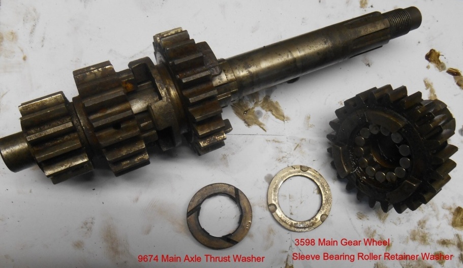
There are some points of attention. The M&I
Manual does not give any figures for the total wear
allowed on the Bronze Clutch Thrust Washer. Additionally, the gearbox exploded
view of the M&I Manual shows a dished washer at the end of the main
shaft, which in many cases is missing in actual gearboxes, and
the same exploded view does not give the Main Gear Wheel Sleeve
Bearing Roller Retaining Washer, which is a crucial part in the
gearbox! (I have drawn this washer into the original gearbox
exploded view below, encircled by a red ring.)
The Clutch Thrust washer is the washer taking up
the reaction forces when the Clutch is operated. Its positioned on
the main axle facing the hardened steel ring that keeps the rollers
of the Main Gear wheel in place. (Main Gear Wheel Sleeve Bearing
Roller Retainer Washer).
The Bronze washer has three grooves in one face, which to be
correctly positioned should be facing towards the Main gear wheel
(Clutch). When these grooves are worn away, the washer needs to be
replaced. The Clutch Thrust washer has a thickness of approximately
7/32 inch (5,55 mm). Maximum permissible wear of the Clutch
Thrust Washer is 1,58 mm or 1/16th inch.
Investigation of the Clutch Thrust washer is indicated when the max
end float of the clutch itself exceeds the 1,6 to 2,38 mm. This can
be roughly inspected by pushing and pulling on the clutch in axial
direction.
End float of the main axle should preferably between 0,254 and 0,508
mm (0,01 - 0,02 inch). If the end float is still outside this range
while the Clutch Thrust washer is within the specified thickness,
the main axle should be shimmed behind the Clutch Worm nut.
This is where the elusive dished washer may be
become handy although flat shims will do the job as well.
The exploded view drawings of the gearbox in the Maintenance and
Instrucion Manual as well as various books, show a dished steel spring
washer at the end of the main axle. Its not given in the spare parts list of either
old or newer contracts or postwar civilian lists. The dimensions are I.D.
5/8", O.D. 1 7/16", steel thickness 1/64" and dished height 1/16"
(as
measured from an actual washer).
Main Gear Wheel Sleeve Bearing Roller Retainer Washer
and Felt Washer for Clutch Nut .
This hardened washer has the tendency to fracture. Two of the 3
gearboxes I have showed this to be the case. The washer is given in the
spare parts lists (all) under spare part no 3598 (Main Gear Wheel Sleeve Bearing
Roller Retainer Washer). I have however not been able to find
original replacements for them, and had them made from a cold work tool
steel (AISI D2 or UNS T30402) and hardened to 59 Rc. Remains of the
original were measured to be 60 Rc so I think I am close enough.
Felt Washer for Clutch Nut, part no. 9744 is also added to the
exploded view below.
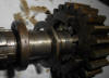
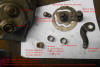
Below also some pictures of various gearbox parts, (source:
Olav Jerzykowski) |

Click to enlarge
One book showing the gearbox in very clear drawings was made by
Niels Schoen, "Norton, Garden Gate Manx" (ISBN 978-90-9029193-2) who
kindly gave permission to show (part off) his meticoulously made drawings of the
gearbox to be replicated here. It is missing the kick starter but it
does give a very detailed picture of the 1935 designed gearbox and
gear change mechanism,
still in use after the war. Part numbers are in the post war
style. Attached scanned copy is to be regarded as reduced quality
version of this
superbly illustrated book.
 click on picture to retrieve pdf file.
|
|
Kickstarter and selector neutral sprin replacements
Unfortunately there are some confusions around the correct
springs for the "Kickstarter Return Spring" (pn 9710) and the
"Return Spring for Pawl Carrier" (pn 3629).
Both items are different for pre- and wartime gearboxes versus most
post war gearboxes. Pictures below show the differences.
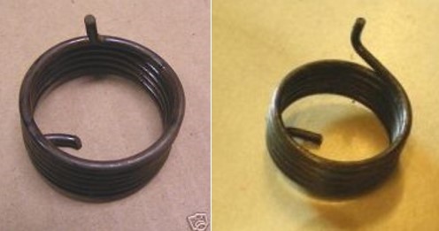
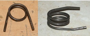
Correct kickstarter spring at left, incorrect version at right.
correct Pawl carrier spring at left, incorrect at right
|
|
Clutch issues
Disengagement
A not uncommon problem encountered when using the MC is that at a
certain moment it appears the clutch cable needs regular adjustment
for a proper clutch release. This is usually caused by the loosening
of the central clutch nut. Contrary to the expectation in the
Instruction and Maintenance manual, a clutch puller is not always
required to remove it from the gearbox axle. A side effect of
a regular adjustment of the clutch cable length may be that at a
certain point, the clutch bolts eat metal away from the outer
primary chain case. The clutch itself is a fairly simple but
effective part.
The original WD clutch back plate was a relatively thin pressed
sheet metal part of even thickness. Post war AMC clutch back plates
are much thicker parts with a chamfered outer edge. They do fit on
the earlier machines as well but there will be even less clearance
between backplate and the primary chain case.
Another source for
disengagement problems can be caused by spring force differences and
possible damages to (almost) sliding faces between cup and stud. The end
plate disc should lift squarely from the plates.
New clutch
plates
I hear many Norton riders complain
about the bad working of the clutch after installing new clutch plates.
New clutch plates made by/to fit AMC upto 1959 fit in WD and other
pre-war Norton clutches.
It keeps dragging a lot. I found out years
ago that the newer plates were slightly thicker than the older ones,
resulting in a minimum play when pulling the clutch lever. This usually
results in continuously dragging plates, leading to gear change
problems, especially when trying to find the neutral position while
standing still. My solution to the
problem has been to just remove one steel and one fiction plate. The
plates will get more "room" to disengage, reducing the drag to a
minimum. With good springs there will not be any slippage, and the front
wheel of the bike can still be lifted from the ground by a sudden clutch
engagement.
If the clutch does show some slippage, the springs could be replaced by
longer ones or some washers can be added
at the bottom of the spring cups, making up some of the thickness of the missing
plates.
Clutch
assembly
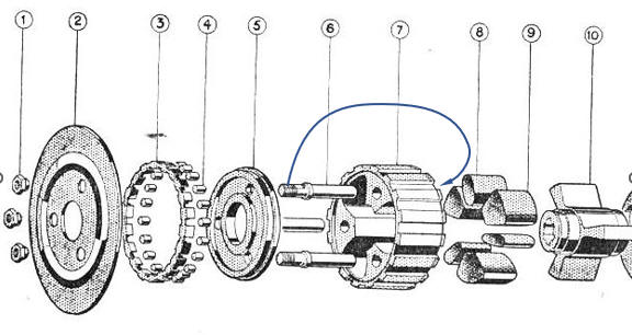
When looking at the exploded view of the clutch, it suggests that
the Clutch Spring Studs (6) are mounted onto the Clutch
Body Back Cover Plate (5) but in actual fact they are used to bolt
the Clutch Body (7) down through the Clutch Body Back Cover Plate
(5) to the
Clutch Back Plate (2) where they are fixed with the hexagon flanged
nuts (1).
 |
|
|
|
