|
Most of the WD Nortons were provided with
speedometers made by Smith, with a maximum reading of 80 MPH. (numbers
given on the number plate are: S.433M
or S.433B/EX or S.434B/EX).
These speedometers work on a chronometric principle were speed is measured in
small increments instead of continuous movement. The intermittent movement of
the needle therefore does not indicate a problem, its just how the instrument
works. Speedometers used for the military Nortons were not provided with trip counters or internal lighting
provisions. Those gadgets were reserved for the civvy market. Norton Assembly
book entries specifically states "80 MPH Speedo, without trip".
Face plates were provided with a bold yellow line at 30 MPH until late 1941
or in 1942 after which the line changed to white.
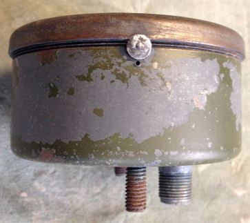
Initially the bezel was pointed and matt chrome plated. From late 1941/early 1942
(no exact date determined yet) onwards they
became rounded and painted in the military colour of the day.
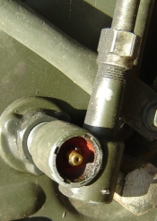
Two types of speedometer to cable connections can be found, the early one with a round protruding
shaft (referred to as Jeager drive) and a later one with
an internal square connection. It is not clear yet as of when the
early Jeager types were changed to the later types. Pictures of bikes from contract V7353
still show the thick cables, which date them at least upto end of 1940, and
possibly even later than that.
The speedometers are actuated through a flexible drive. These also come in
two variations, each fitting to the specific connection on the speedometer.
The Jeager drive cables consisted of an approximately 3 mm diameter
inner flex which ran through a rubber covered steel outer flex with a .. mm
11 inner diameter. The illustrated
parts list picture shows the Jeager type (large diameter)
cable/connection.
The later cables are basically modern cables as still used today.
The bottom part of both cable types consists of a spade like protrusion
which is fitted in the gearbox and secured with a nut. The top part of the
cable is either a tube, fitted over
the Jeager drive or a square deformed end of the inner cable which slides up
into the speedometer connection and screwed tight.
The length of both early and later type cables is identical, 25 inch. It
appears that the later speedo bracket offset upwards was intended to keep
the cable length standard for all MC's.
The front wheel is provided with a
gear ring (43 teeths) screwed onto the hub of the front brake drum. A gearbox is
fitted to the front brake plate provided with a pinion (14 teeths) meshing with the gear
ring. Speedo gearboxes can be found with different gear ratios and different
rotation direction. The output drive has to be clockwise when looking from
above into the slot. (Rotate pinion anti-clock). Three (3) turns on the
pinion gives two (2) turns of the inner cable. Smith indicates this as 8 :
12 gear ration in their folders.
There are two different lengths of mounting screw thread described as "long
reach" and "short reach". Norton requires the long reach version (approx
30mm).
Early motorcycles had a centrally mounted
Speedometer. The earliest contract (based on pictures) showing a left hand mounted speedometer was C6127
of which the first bikes were delivered in May 1940. The spare parts list for
this contract however still refers to the centrally mounted part number 3884.
The spare parts list of V7353
shows
the left hand sided mounting (spare part no. 4114) superseding the centrally mounted version. This
more or less indicates that at least all bikes with frame numbers above W26000
were provided with the left hand mounted speedometers. Early type of
holders were all of constant width on the horizontal mounting. This was
later modified with a wider section at the left hand grease nipple/mounting
bolt.
Despite its apparent water tight appearance, these
instruments do collect water inside. Drying out can help prevent damage to the
internals. As can be seen in the picture, my milage drum has suffered from
corrosion, and I did once repair a malfunction by cleaning and drying out the
inside.
This did unfortunately require me to remove the original anti-tamper rivet
in order to be able to screw off the bezel.
The "Motor Cycle" magazine of April 1992
shows how to execute a
revision/clean up of this type of speedometer.
|
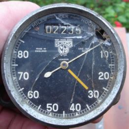
Smiths early model with pointed, matt chrome bezel
|
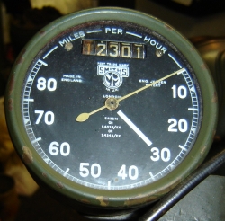
Smiths late model with rounded, painted bezel
|
|
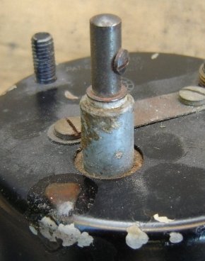
Speedometer, early model "Jeager" type
connection inner cable sliding over protrusion and outer cable sliding
over the housing and clamped tight with a strap
|
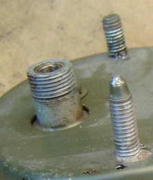
Speedometer later model with internal square and
screw-on outer cable (stud in foreground not original)
|
|
Anti-tamper rivet, early versions with Smiths engraved in its head
|
Speedometer front wheel hub gear box
|
|
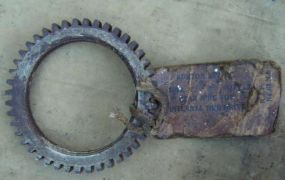
Speedo drum gear ring, 43 teeths
|
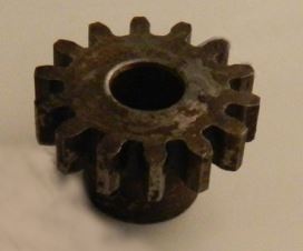
Speedo pinion, 14 teeths |
|