|
|
Electrical system (iss 135) |
Back to change notice |
|
|
Electrical system (iss 135) |
Back to change notice |
|
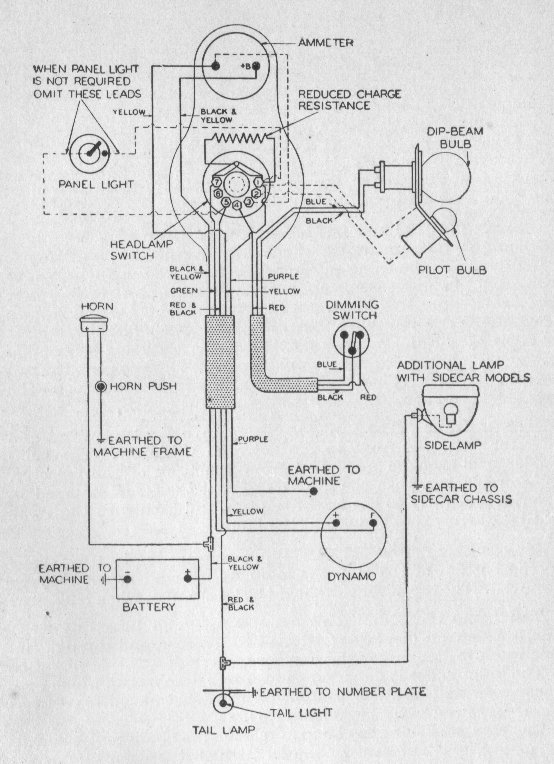
Wiring diagrams:
For
military Nortons, a number of 6V
negative (-) earth
systems have been used based on the existing equipment or the
operational requirements of the time at which they were applied. It was a
relative simple system and used
by most of the contemporary British motorcycle manufacturers. Some used
Miller equipment. "Lucas
invented darkness" or Lucas "Prince of darkness" are some of
the many adjectives for the products of Lucas manufacture. Many of the
problems were caused by bad maintenance or by the harsh environment into
which the bikes were operated.
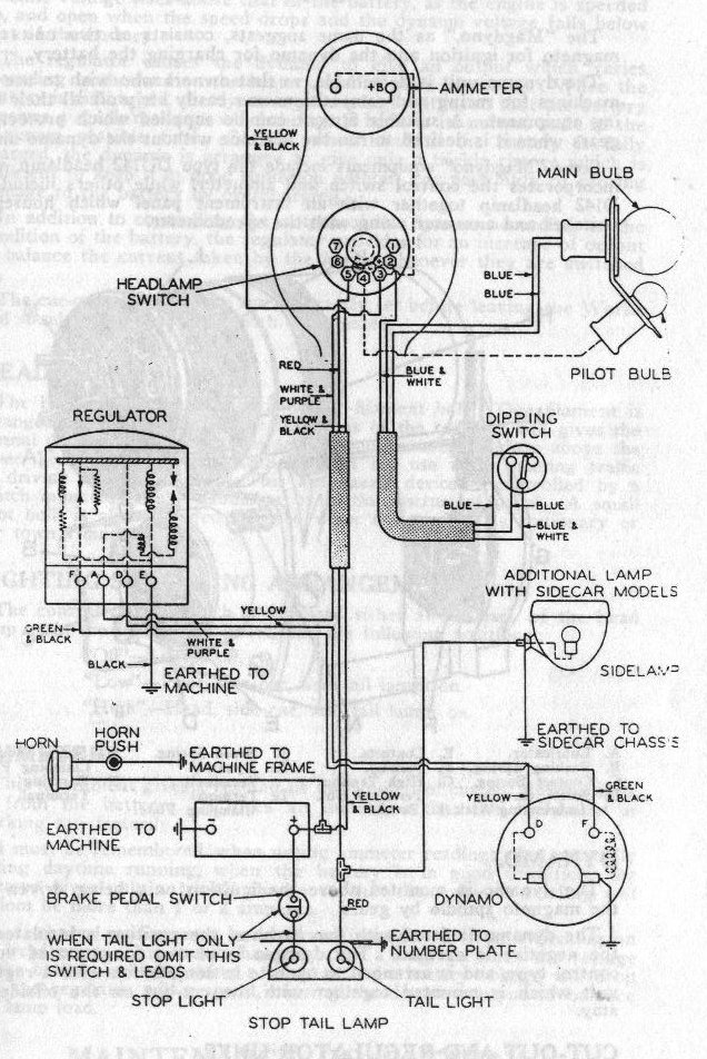
Electrical equipment variation two:
The wiring diagram changed over time based on operational requirements.
On May 5th 1941, DME Circular B.141 mandated the removal of the Dipper
switch from the existing motorcycles and the fitting of new headlamp masks
(black-out).
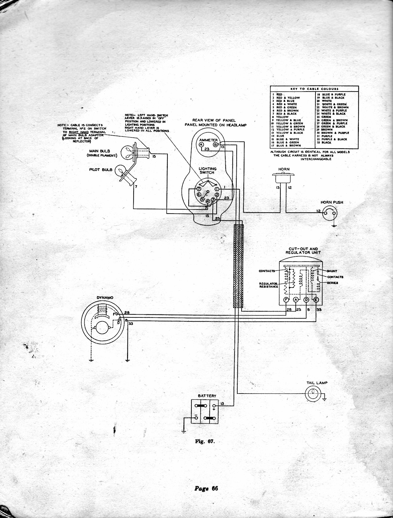
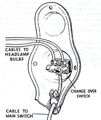
Nearing the end of the war, an "improved" wiring scheme was
introduced, to reduce the number of wires running from the front fork to
the rest of the machine after it was recognised that many electrical
faults developed through chafing, resulting from the continues movement of
the front fork. This system was also introduced on other brand motorcycles
like the BSA M20.
| ||||||||||||||||||||||||||||||||||
16H |
16H |
16H |

Big 4 |
  1944/45 upwards
| ||||||||||||||||||||||||||||||
|
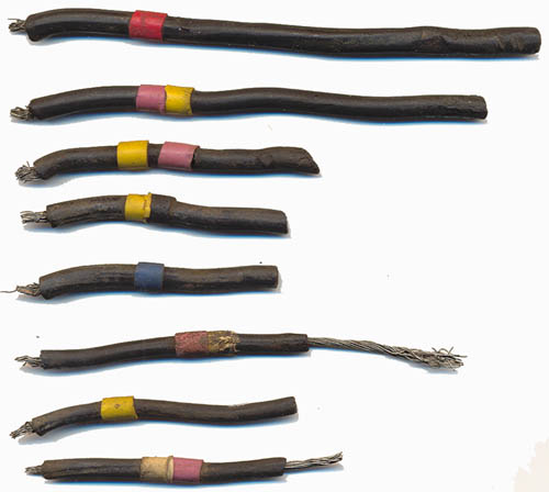
Wires:
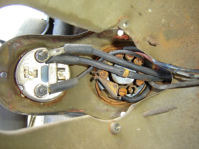
Remains of original wires found on a switch as applied in the late
war electrical system (1944/45) appeared to be rubber like, similar as
described above.
At least 2 different diameter wires have been found, approximately Ø 4,6 mm and Ø 5,7 mm as measured on the insulation. Wiring remains on a late-war (re?)built machine showed to have cloth covered leads. It was not possible to assure this was factory applied. Whether the use of the cloth encapsulated wire was widespread is difficult to say. Cloth encapsulated wiring was used on motorcars and motorcycles in the 20ties and 30ties.
Wiring
harness and
wire fixing
Batteries and CVC
(Constant Voltage Control, MCR1)
regulators Because of the different charging requirements there were also two types of MCR1 CVC regulators. It is believed that prior to the introduction of the lead acid batteries by the military, civilian regulators did not have a battery type marking and that Ni-Fe type regulators were marked "NI-FE" on the front bottom of the regulator above the F A D E markings.
With the introduction of the lead acid battery by the military (late
1939) the lead acid battery regulators were marked with "LEAD-ACID",
likely to assure the application of the correct regulator. Lead Acid batteries could work with Ni-Fe CVC's but it was only allowed for a short period and not recommended.
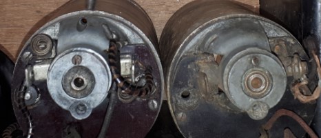
Dynamo's E3.HM
Magneto
variations
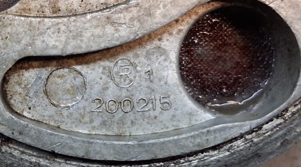
The Electrical equipment picture page gives some indication on what the different parts basically look like. Many
(but not all) Lucas parts are provided with the manufacturing date stamped into them. If
you really want to restore a bike to "factory" fresh condition,
searching for correctly dated Lucas equipment should make your life
exciting.
| ||||||||||||||||||||||||||||||||||
![]()
 Picture from article of Steve Madden, courtesy Henk Joore's
WDBSA.nl website.
Picture from article of Steve Madden, courtesy Henk Joore's
WDBSA.nl website.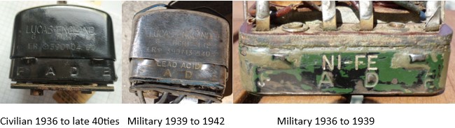
,%20200216%20at%20right.jpg)